1. Introduction
To give the best performance, KROHNE level meters must be installed in a correct way. Important instructions should be taken into consideration, like the mounting position, shape of the tank, obstacles within the tank, etc. Depending on the measuring principle of each device, the guidelines will differ. In this article we will explain the installation instructions for Non Contact Radar Level meters for liquid measurements (OPTIWAVE 7x00 & OPTIWAVE 5x00).
The article cover the following topics:
- General Installation Notes
- OPTIWAVE 5200
- OPTIWAVE 5400
- OPTIWAVE 7300
- OPTIWAVE 7400
- OPTIWAVE 7500
- The mounting position of the measuring device is an important parameter for the attainable measuring quality. Mount the device at a site that rules out deposits and minimizes the impact of obstacles. The unrestricted "free view" of the product surface is the prime goal.
- Make sure that the entire radar beam doesn’t come into contact with the wall of the vessel or obstacles within the tank.
- There should be a sufficient distance between the nozzle and the antenna as well as the filling stream to avoid interference with the radar beam

- Possible product deposits should be taken into account, especially in the case of adhesive liquids or bulk solids.
- It is always recommended to keep any existing connection nozzle as short as possible so that the standard length radar antennas are slightly longer.

- If there are too many obstacles in the tank or the tank geometry is unfavorable; if the liquid has a poor reflective or is highly turbulent; or if highly conductive foam is present - alternatives such as stilling wells, wave guide antennas or lateral reference chambers should be considered. These alternatives can be used for non-adhesive products and those that are not highly viscous.

- Stilling wells are smoothing pipes in the length of the measuring range, mounted into the tank from above. They have lateral pipe openings to ventilate as well as to achieve a better product mix. The outer diameter of metallic horn antennas used in stilling wells is specifically adapted to the inner diameter of the stilling wells.
- Radar devices are also used on lateral, metallic reference chambers. Like stilling wells, these radar devices have antennas specifically adapted to the diameter of the reference chamber.
3. OPTIWAVE 5200
Mount the sockets and nozzles for different antenna like shown in the picture below, where:
- Sockets for the PP Wave Horn antenna.
- Nozzles for the PTFE Wave Horn antenna.
- Nozzles for DN150 or DN200 Metallic Horn antennas.
- Nozzles for Wave Guide antennas.
- Tank diameter.
-
Minimum distance of the nozzle or socket from the tank wall (depends on the antenna type and size):
- PP/PTFE Wave Horn (1 and 2) = 1/7 × tank height.
- Metallic Horn (3) = 1/10 × tank height.
-
Wave Guide (4) There is no minimum distance from the Wave Guide antenna to metallic walls and other metal objects. Maximum distance of nozzle from the tank wall (depends on the antenna type and size):
- PP/PTFE Wave Horn (1 and 2) =1/3 × tank diameter.
- Metallic Horn (3) = 1/3 × tank diameter.
- Wave Guide (4). There is no maximum distance from the Wave Guide antenna to metallic walls and other metal objects.
- Tank height.

- If there is a nozzle on the tank before installation, the nozzle must be a minimum of 200 mm / 7.9¨ from the tank wall. The tank wall must be flat and there must not be obstacles adjacent to the nozzle or on the tank wall.
- Point the device in the correct direction by Pointing the tag hole on the housing in the direction of the nearest tank wall.

- Dish-shaped or conical bottoms for a tank have an effect on the measuring range. The device cannot measure to the bottom of the tank.

- Do not tilt the device more than 2° (see picture below).
- We recommend that you do an empty spectrum recording if there are obstacles in the radar beam. If necessary, install a bypass chamber or stilling well or use an S-bend antenna extension or an L-bend antenna extension (the device must be installed on the side of the tank) to move the device away from obstacles.
- The inside diameter of the standpipe must not be more than 5 mm / 0.2¨ over the diameter of the antenna (for a high-dielectric constant liquid).

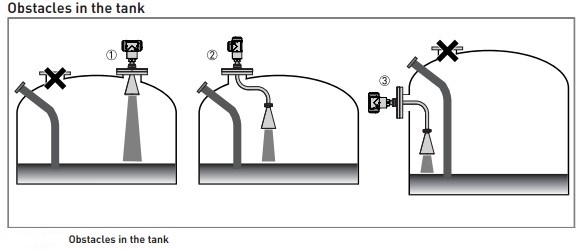
- Do not put the device directly above obstacles (agitator, support beams, heating tubes etc.). Parasitic signals from obstacles will cause the device to measure incorrectly, rather
- Put the device on another process connection away from obstacles.
- Use the same process connection, but also use an S-bend extension.
- Attach the device to the side of the tank and use an L-bend (right angle) extension
- Do not put the device near to the product inlet. If the product that enters the tank touches the antenna, the device will measure incorrectly. If the product fills the tank directly below the antenna, the device will also measure incorrectly.

- In case of using stand pipes stilling wells and bypass chamber:
- The standpipe must be electrically conductive.
- The inside diameter of the standpipe must not be more than 5 mm / 0.2¨ over the diameter of the antenna (for a high-dielectric constant liquid).
- The standpipe must be straight. There must be no sudden changes in internal diameter greater than 1 mm / 0.04¨.
- The standpipe must be vertical.
- Recommended surface roughness: <±0.1 mm / 0.004¨.
- Make sure that there are no deposits at the bottom of the standpipe.
- Make sure that there is liquid in the standpipe.

Nozzle or socket for the DN40 or DN50 Metallic Horn antennas
- Nozzle or socket for the DN80 or DN100 Metallic Horn antenna, and the DN80 Drop antenna
- Nozzle or socket for the DN150 or DN200 Metallic Horn antenna, and the DN100 or DN150 Drop antenna
- Tank diameter
- Minimum distance of the nozzle or socket from the tank wall (depends on the antenna type and size – refer to items1, 2 and 3 in this list):

- If there is a nozzle on the tank before installation, the nozzle must be a minimum of 200 mm /7.9¨ from the tank wall. The tank wall must be flat and there must not be obstacles adjacent to the nozzle or on the tank wall.
-
Point the device in the correct direction to get the best performance.
-
Dish-shaped or conical bottoms have an effect on the measuring range. The device cannot measure to the bottom of the tank. If possible, install the device as shown in the illustration that follows:
- Do not install the device above objects in the tank (ladder, supports etc.) or pit, objects in the tank or pit can cause interference signals. If there are interference signals, the device will not measure correctly,causes for interference signal includes:
- Objects in the tank or pit.
- Sharp corners that are perpendicular to the path of the radar beam.
- Sudden changes in tank diameter in the path of the radar beam.
- If it is not possible to install the device on another part of the tank or pit, do an empty spectrum scan.
- If there are too many obstacles in the tank, you can install the device on a standpipe.
- Do not put the device near to the product inlet. If the product that enters the tank touches the antenna, the device will measure incorrectly, if the product fills the tank directly below the antenna, the device will also measure incorrectly.
- In case of stand pipe / stilling wells:
- The standpipe must be electrically conductive
- The inside diameter of the standpipe must not be more than 5 mm / 0.2¨ over the diameter of the antenna (for a high-dielectric constant liquid).
- The standpipe must be straight, there must be no sudden changes in internal diameter greater than 1 mm / 0.04¨.
- The standpipe must be vertical.
- Recommended surface roughness: <±0.1 mm / 0.004¨.
- Make sure that there are no deposits at the bottom of the standpipe.
- Make sure that there is liquid in the standpipe.
- For stilling wells, drill an air circulation hole (max. Ø10 mm / 0.4¨) in the stilling well above the maximum level, drill 1 or more liquid circulation holes in the stilling well (if there is more than 1 liquid in the tank),these holes help the liquid to move freely between the stilling well and the tank.
- In case of installing in bypass:
- The top process connection of the bypass chamber must be above the maximum level of liquid
- The bottom process connection of the bypass chamber must be below the lowest measured level of liquid
- Additional process connections are necessary for the liquids to circulate freely along the length of the bypass chamber for more than one liquid in the tank.


- Nozzles for DN40 or DN50 Horn antennas, or DN50 Hygienic antenna.
- Nozzles for DN80, DN100, DN150 or DN200 Horn antennas and DN80 or DN150 Drop antennas.
- Tank height.
- Tank diameter.
- Minimum distance of nozzle from the tank wall : 1/7 × tank height Maximum distance of nozzle from the tank wall : 1/3 × tank diameter.
- Minimum distance of nozzle from the tank wall : 1/10 × tank height Maximum distance of nozzle from the tank wall : 1/3 × tank diameter.

- Do not put the device near to the product inlet. If the product that enters the tank touches the antenna, the device will measure incorrectly. If the product fills the tank directly below the antenna, the device will also measure incorrectly.

- To make the cleaning of the antenna easier, attach the device to a short socket.

- Do not tilt the device more than 2°
- We recommend that you do an empty spectrum recording if there are too many obstacles in the radar beam (for more data, refer to How to make a filter to remove radar signal interference on page 75), or install a bypass chamber or stilling well.
- In case of using standpipes, the inside diameter of the standpipe must not be more than 5 mm / 0.2¨ over the diameter of the antenna (for a high-dielectric constant liquid).

- In case of using stand pipes stilling wells and bypass chamber:
- The standpipe must be electrically conductive.
- The inside diameter of the standpipe must not be more than 5 mm / 0.2¨ over the diameter of the antenna (for a high-dielectric constant liquid).
- The standpipe must be straight. There must be no sudden changes in internal diameter greater than 1 mm / 0.04¨. • The standpipe must be vertical.
- Recommended surface roughness: <±0.1 mm / 0.004¨.
- Stilling well only: The bottom of the stilling well must be open.
- Make sure that there are no deposits at the bottom of the standpipe.
- Make sure that there is liquid in the standpipe.

6. OPTIWAVE 7400
- Nozzle or socket for the DN40 or DN50 Metallic Horn antennas.
- Nozzle or socket for the DN80 or DN100 Metallic Horn antenna, and the DN80 Drop antenna.
- Nozzle or socket for the DN150 or DN200 Metallic Horn antenna, and the DN100 or DN150 Drop antenna.
- Tank diameter.
-
Minimum distance of the nozzle or socket from the tank wall (depends on the antenna type and size – refer to items1, 2 and 3 in this list):
- DN40 or DN50 Metallic Horn: 1/5 × tank height
- DN80 or DN100 Metallic Horn: 1/10 × tank height
- DN80 Drop: 1/10 × tank height
- DN150 or DN200 Metallic Horn: 1/20 × tank height
- DN100 or DN150 Drop: 1/20 × tank height
- Maximum distance of the nozzle or socket from the tank wall (depends on the antenna type and size – refer to items1, 2 and 3 in this list)
- Metallic Horn or Drop: 1/3 × tank diameter
- Tank height

- If there is a nozzle on the tank before installation, the nozzle must be a minimum of 200 mm /7.9¨ from the tank wall. The tank wall must be flat and there must not be obstacles adjacent to the nozzle or on the tank wall.
- Point the device in the correct direction to get the best performance while
- Cable entry.
- Nearest tank wall.
- Tank center line

- There is no maximum limit to the number of devices that can be operated in the same tank. They can be installed adjacent to other radar level transmitters.
- Dish-shaped or conical bottoms have an effect on the measuring range. The device cannot measure to the bottom of the tank. If possible, install the device as shown in the illustration that follows where :
- Axis of radar beam.
- Minimum level reading

- Do not install the device above objects in the tank (agitator etc.) or pit. Objects in the tank or pit can cause interference signals. If there are interference signals, the device will not measure correctly.
- If it is not possible to install the device on another part of the tank or pit, do an empty spectrum scan.
- take in considration the following recommendations:
- Do not tilt the device more than 2°.
- We recommend that you do an empty spectrum recording if there are too many obstacles in the radar beam
- If there are too many obstacles in the tank, you can install the device on a standpipe. For more data about how to install the device on standpipes, refer to Standpipes (stilling wells and bypass chambers) on page 35.
- Beam radius of the antenna: refer to the table below. The beam radius increases by increments of "x" mm for each metre of distance from the antenna.


- Do not put the device near to the product inlet. If the product that enters the tank touches the antenna, the device will measure incorrectly. If the product fills the tank directly below the antenna, the device will also measure incorrectly.

- Use Standpipes (stilling wells and bypass chambers) in case of the following (with Metallic Horn antenna options only):
- There is highly conductive foam in the tank.
- The liquid is very turbulent or agitated.
- There are too many other objects in the tank.
- The device is measuring a liquid (petro-chemicals) in a tank with a floating roof.
- The device is installed in a horizontal cylindrical tank.

- In case of using stand pipe, kindly note the following:
- The standpipe must be electrically conductive.
- The inside diameter of the standpipe must not be more than 5 mm / 0.2¨ over the diameter of the antenna (for a high-dielectric constant liquid).
- The standpipe must be straight. There must be no sudden changes in internal diameter greater than 1 mm / 0.04¨.
- The standpipe must be vertical.
- Recommended surface roughness: <±0.1 mm / 0.004¨.
- Make sure that there are no deposits at the bottom of the standpipe.
- Make sure that there is liquid in the standpipe
- In case of Stilling wells, you must drill an air circulation hole.:
- In tanks containing one liquid and foam, drill an air circulation hole (max. Ø10 mm / 0.4¨) in the stilling well above the maximum level.
- In tanks containing one liquid or more without foam, drill an air circulation hole (max. Ø10 mm / 0.4¨) in the stilling well above the maximum level. Drill 1 or more liquid circulation holes in the stilling well (if there is more than 1 liquid in the tank), these holes help the liquid to move freely between the stilling well and the tank.
-
In case of Bypass chambers:
For tanks containing one liquid and foam, the top process connection of the bypass chamber must be above the maximum level of liquid, the bottom process connection of the bypass chamber must be below the lowest measured level of liquid.
- For tanks containing more than one liquid, the top process connection of the bypass chamber must be above the maximum level of liquid, the bottom process connection of the bypass chamber must be below the lowest measured level of liquid.
- Nozzle or socket for the DN20 or DN25 Lens antenna.
- Nozzle or socket for the DN40 or DN70 Lens antenna.
- Tank diameter
- Minimum distance of the nozzle or socket from the tank wall (depends on the antenna type and size – refer to item 1 in this list)
- DN20 or DN25 Lens : 1/5 × tank height.
- DN40 Lens: 1/10 × tank height.
- DN70 Lens: 1/20 × tank height Maximum distance of the nozzle or socket from the tank wall (depends on the antenna type and size – refer to item 1 in this list).
- Lens: 1/3 × tank diameter.
- Tank height

- If there is a nozzle on the tank before installation, the nozzle must be a minimum of 200 mm /7.9¨ from the tank wall. The tank wall must be flat and there must not be obstacles adjacent to the nozzle or on the tank wall.
- Point the device in the correct direction to get the best performance while
- Cable entry.
- Nearest tank wall.
- Tank center line
There is no maximum limit to the number of devices that can be operated in the same tank. They can be installed adjacent to other radar level transmitters.
Dish-shaped or conical bottoms have an effect on the measuring range. The device cannot measure to the bottom of the tank. If possible, install the device as shown in the illustration that follows where :
- Axis of radar beam.
- Minimum level reading
-
take in consideration the following recommendations:
- Do not tilt the device more than 2°.
- We recommend that you do an empty spectrum recording if there are too many obstacles in the radar beam
- Beam radius of the antenna: refer to the table below. The beam radius increases by increments of "x" mm for each metre of distance from the antenna.
- Do not put the device near to the product inlet. If the product that enters the tank touches the antenna, the device will measure incorrectly. If the product fills the tank directly below the antenna, the device will also measure incorrectly.


